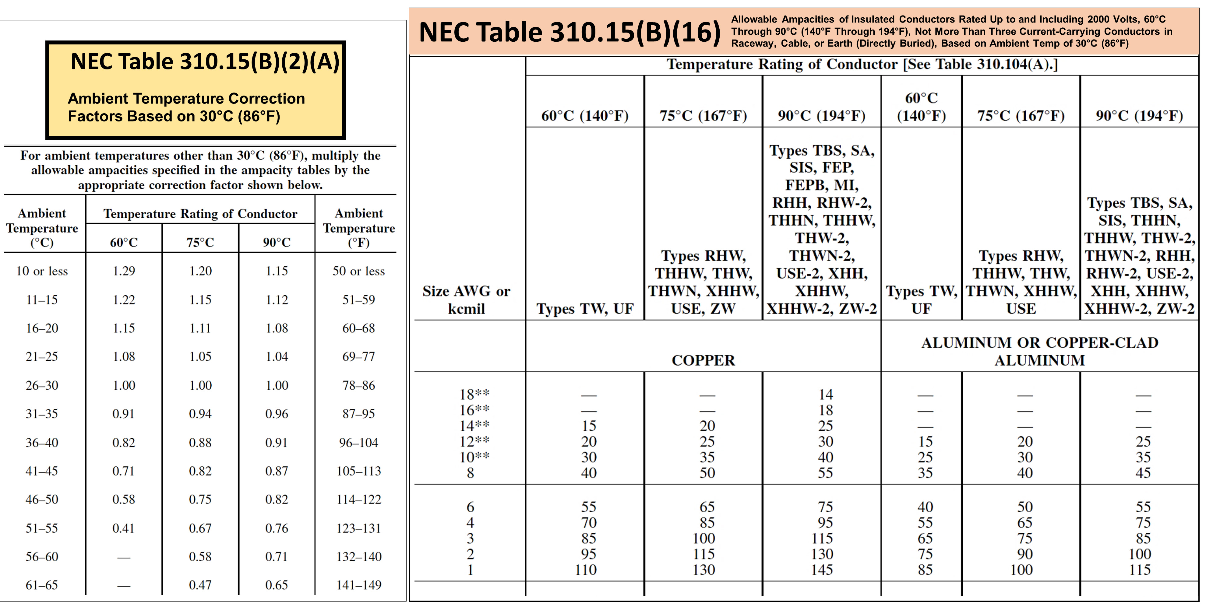

Overall system requirements – Consider the load and maximum temperature rating of the devices and equipment that make up the electrical system.In these cases, the wire size is selected such that the temperature rise of the wire does not exceed 30☌. Electrical motors, for example, draw a large amount of current at start up for a short period of time and then the current level reduces as the motor reaches the steady state rpm. Duty cycle – many times the level of current in applications will vary over time depending on the type of loads.In this example, the Ampacity of the conductor size specified will need to be de-rated by 50% (based on being limited to a 15☌ rise instead of a 30☌ rise). If the temperature rating of a wire is 90☌ and it needs to be placed in a 75☌ ambient condition, then the allowable temperature rise of the wire is 15☌ (90☌ minus 75☌).


The quotient is the expected Amperage of the circuit. Ampacity can be calculated by dividing the Wattage by the rated voltage. It is not un-common for devices to be marked with load size (like Wattage or Amps and Volts). The load is what will determine the level of current in the system. The conductor size selected needs to match the electrical load.

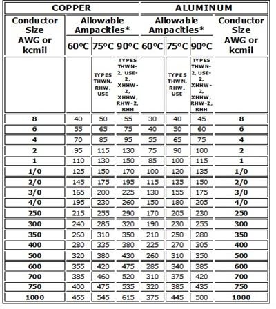
The ampacity rating of higher temperature rated wires is greater than lower temperature rated wires for any given size of conductor. The ampacity of the wire is determined by the amount of current in the wire at the point in which the conductor’s temperature rises 30☌. If more than 3 wires carry current in a raceway, then you will have to de-rate the ampacity of the wires based on the factors provided by Article 310.
#WIRE AMPACITY CHART FREE#
The tables show the ampacities as wires in free air and up to 3 wires in a raceway (this includes conduit, cable jackets, etc).
#WIRE AMPACITY CHART CODE#


 0 kommentar(er)
